OSI PROTOCOL
Layered model
For one application to communicate with another across a network, quite a complex
process must be gone through. For example, the other application must be found,
a link needs to be established and maintained, possibly using telephone links
or optic cable. Noise and losses must be handled and all the errors that can
occur.
For an application to handle all this is too hard, so layers of abstraction
are used.
The major model is the ISO OSI model (International Standards Organisation
Open Systems Interconnection model). This is a 7-layered model
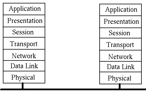
When a process on Machine A wishes to talk to a process on Machine B it builds
a message as a set of bytes that the two applications understand (eg a null
terminated string, a record data type).
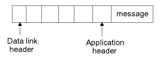
It passes this to the Application layer, which adds an information header to
the message. This will then be used by the Application layer on the other side
of the link to use.
The Application layer passes it down to the Presentation layer which also adds
a header. This continues down to the Physical layer which finally sends it
along the network.
Why so complex? The boss says ``Take a memo to Fred...'' The Secretary looks
up Fred's address, puts it on the envelope and drops it in the mail bag. The
Mail Room collects the bag later, sorts the mail into internal and external,
and puts a stamp on the envelope. The Post Office collects it later, and franks
the envelope.
At the other end, the Mail Room delivers the letter to the right section, the
Secretary to the right person, the person opens the envelope to read the letter.
At each stage on the way down, each layer adds more information and uses different
bits of information, and on the way back up this information is used in reverse.
Physical layer
This transmits the bits of the combined message.
Data link layer
This adds error checking to the physical layer by adding a checksum before
sending and seeing if this is ok at the receiving end. If an error occurs then
retransmission of the message will be requested.
Network layer
The network layer looks after the route that the message will follow to get
between the two machines. This may be connection-oriented or connectionless.
In the connection-oriented method the route is established and the message
sent along it. Further messages are sent by the same route. An example is the
X.25 protocol.
In the connectionless method each message will be sent separately, possibly
by different routes taking different amounts of time. An example is the IP
(Internet Protocol).
Transport layer
Generally more than one message will be sent between the applications. They
must all arrive and in the correct order. In practise some will be lost and
they may arrive out of order. The transport layer looks after these problems
so that the higher layers can assume that no errors occur.
Session layer
This provides dialog control, synchronisation and checkpointing.
Presentation layer
This layer puts information about the message type into its header, so that
the message is more than just a collection of bytes.
Application layer
This provides high level services such as the X.400 mail protocol and the X.500
Directory services.
TCP/IP
Another protocol?
The OSI model was devised using a committee process wherein the standard was
set up and then implemented. Some parts of the OSI standard are obscure, some
parts cannot easily be implemented, some parts have not been implemented.
The TCP/IP protocol was devised through a long-running DARPA project. This
worked by implementation followed by RFCs (Request For Comment). TCP/IP is
the principal Unix networking protocol. TCP/IP = Transmission Control Protocol/Internet
Protocol.
TCP/IP stack
The TCP/IP stack is shorter than the OSI one:
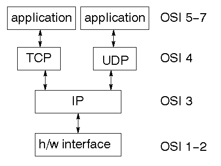
TCP is a connection-oriented protocol, UDP (User Datagram Protocol) is a connectionless
protocol.
IP datagrams
The IP layer provides a connectionless and unreliable delivery system. It considers
each datagram independently of the others. Any association between datagrams
must be supplied by the higher layers.
The IP layer supplies a checksum that includes its own header. The header includes
the source and destination addresses.
The IP layer handles routing through an Internet. It is also responsible for
breaking up large datagrams into smaller ones for transmission and reassembling
them at the other end.
UDP
UDP is also connectionless and unreliable. What it adds to IP is a checksum
for the contents of the datagram and port numbers. These are used to give a
client/server model - see later.
TCP
TCP supplies logic to give a reliable connection-oriented protocol above IP.
It provides a virtual circuit that two processes can use to communicate.
Client-Server Model
The existence of a protocol does not give much structure to communication.
In the client-server model a set of processes offer services to suitable clients.
A server may be a file server so that when a request is received it retrieves,
modifies, removes, etc files.
A server may be a database server so that when it receives a request it accesses,
modifies, etc the database.
A server may be a password server that verifies whether or not a password is
valid.
Clients are other processes that require these services. A client will create
a message in the format that the server wants. It will then send the request
to the server, which will take suitable action. It may make a reply to the
client, or even request more information.
Internet adddresses
In order to use a service you must be able to find it. The Internet uses an
address scheme for machines so that they can be located.
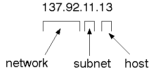
The address is a 32 bit integer which gives the IP address. This encodes a
network ID and more addressing. The network ID falls into various classes according
to the size of the network address.
Network address
-
Class A use 8 bits for the network address with 24 bits left over for other
addressing.
-
Class B uses 16 bit network addressing.
-
Class C uses 24 bit network
addressing.
-
Class D uses all 32.
The University of Canberra is registered as a Class B network, so we have a
16 bit network address with 16 bits left to identify each machine.
Subnet address
Internally, the Uni network is divided into subnetworks. 8 bits are used for
this. Building 11 is currently on one subnetwork.
Host address
8 bits are finally used for host addresses within our subnet. This places a
limit of 256 machines that can be on the subnet.
Total address
The 32 bit address is usually written as 4 integers separated by dots
Symbolic names
Each host has a name. This can be found from the user level command
hostname
A symbolic name for the network also exists. For our network it is ``canberra.edu.au''.
The symbolic network name for any host is formed from the two:
birch.canberra.edu.au
Programming interface
The BSD library provides some functions for finding names.
char *gethostname(char *name,
int size)
finds the ordinary hostname.
struct hostent
*gethostbyname(char *name)
returns a pointer to a structure with two important fields:``char * h_name''
which is the ``official'' network name of the host and ``char **h_addr_list''
which is a list of TCP/IP addresses.
struct hostent {
char *h_name;
char **h_addr_list;
...
}
A little grotty bit: h_addr_list is actually an array of pointers to a
structure of type in_addr, so has to be coerced to that type. Type in_addr
is the address in network byte order, so in order to use it locally you have
to convert it to local byte order using inet_ntoa().
The following program prints host name and address:
This programming interface uses a number of standard files: /etc/hostname to
find the name, /etc/rhosts to find the network address (or a name server) if
it can't find it there.
Port addresses
A service exists on a host, and is identified by its port. This is a 16 bit
number. To send a message to a server you send it to the port for that service
of the host that it is running on. This is not location transparency!
Certain of these ports are ``well known''. They are listed in the file /etc/services.
For example,
- ftp: 21/tcp
- time: 37/tcp
- time: 37/udp
- finger 79/tcp
Ports in the region 1-255 are reserved by TCP/IP. The system may reserve more.
User processes may have their own ports above 1023.
The function ``getservbyname'' can be used to find the port for a service that
is registered in /etc/services.
Berkeley sockets
When you know how to reach a service via its network and port IDs, what then?
If you are a client you need an API that will allow you to send messages to
that service and read replies from it.
If you are a server, you need to be able to create a port and listen at it.
When a message comes in you need to be able to read and write to it.
Berkeley sockets are the BSD Unix system calls for this. They are part of the
BSD Unix kernel. More on this next week...
Remote Procedure Call
The idea of sending messages from one process to another is not reflected directly
in most programming languages. In the procedural languages a major mechanism
is the procedure call. Is it possible to do procedure calls across a network?
Yes, but it is a topic left till later.
Data representation
Some computers are ``big endian''. This refers to the representation of objects
such as integers within a word. A big endian machine stores them in the expected
way: the high byte of an integer is stored in the leftmost byte, while the
low byte of an integer is stored in the rightmost byte. A Sun Sparc is big
endian. So the number 5 + 6 * 256 would be stored as
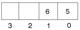
A ``little endian'' machine stores them the other way. The 386 is little endian.
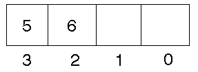
If a Sparc sends an integer to a 386, what happens? The 386 sees 5 + 6 * 256
as
5 *16777216 + 6 * 65536
To avoid this, two communicating machines must agree on data representation.
The Sun RPC uses a format known as XDR, which just happens to be the format
that doesn't require any conversions for Suns. However, if two 386s are communicating
then each of them will have to keep swapping bytes both on receipt and send.
The OSF DCE uses native format, with the receiving machine swapping bytes if
needed.
This page is
http://pandonia.canberra.edu.au/OS/l12_2.html,
copyright Jan Newmarch.
It is maintained by Jan Newmarch.
email:
jan@ise.canberra.edu.au
Web:
http://pandonia.canberra.edu.au/
Last modified: 6 October, 1995


