Lanbon make a range of light switches with Wifi access. They can be integrated into Amazon Alexa and Google Home. I have three switches, a single-gang, double-gang and dimmable switch, all model L6 (I think). I had a lot of trouble pairing my switches to my Xiaomi mobile phone, and in the end had to change mobile phones, which doesn't sound right.
There is an Android phone app which can be used to control
the switches once paired.
The app asks for an outrageous set of permissions, including
making phone calls, reading address book, etc.
Mine looks like
In order to find out what the phone was doing, I used wireshark. Wireshark showed that typically requests to do something from the phone to the switch were sent to a cloud service at 47.52.5.108. An Apache server lives there, home page unconfigured. The packets are sent over HTTPS so it is not possible to see their contents.
Each switch is running an ordinary HTTP server on port 80. It
is password protected: admin/admin - so hard to guess :-).
It gives info in Chinese.
Nothing unusual, apart from listing an SSID of lanbon
with password lanbon1234.
Presumably this is when it is running in access point mode,
waiting to be configured.
My three switches are on 10.0.237.107, 10.0.237.129 and 10.0.237.128
Occasionally, wireshark would pick up that commands were not always sent to the remote server, but were sent on the local LAN. These are broadcast UDP packets sent to 255.255.255.255, port 8866.
Thus it appears that there is a LAN mode, just like there is for many other home IoT devices such as Yeelight, LIFX and others.
However, the Lanbon LAN mode is not documented, unlike the LIFX and Yeelight modes. Private emails from Lanbon say that if I buy 2,000 switches I will be given access to an API, presumably the one I have found. But presumably I would also have to sign a Non-Disclosure Agreement. Since I don't have the necessary A$200,000, the moral issue doesn't arise :-).
By running wireshark in promiscuous mode I can see many of the packets travelling across my wireless LAN. Occasionally I see command packets from the app on my mobile phone to a Lanbon switch. These are broadcast to 255.255.255.255 to port 8866. I have partially decoded them, but not completely successful yet.
As an experiment, I disconnected the router from the internet, so that "dialling home" would not be possible. The mobile phone app tried to connect to the external Lanbon site, but on failure broadcast to the LAN address 10.0.237.255 (their current internal network is 10.0.237.0/24). The content is the same as the broadcasts to 255.255.255.255.
Each packet has 33 bytes of data, a mixture of device identifier, the command and lots of fixed data that I don't understand. For example, the command to the dual ganged switch with one off and the other on is
0000 aa 21 a0 10 ae 20 15 04 63 86 02 01 00 21 a0 10
0010 00 00 00 00 00 00 00 00 00 00 00 00 00 00 00 00
0020 00
Originally I had no idea about any of them, but patterns emerged.
Also, from the app, you can hold down the icon for a
switch and it will bring up a 'management mode'
that gives lots of information, including the device
identifier.
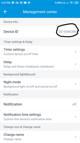
For the switch above, the device identifier is "2015046386", and this is seen in bytes 5 to 9 inclusive (numbered from zero upwards).
0000 aa 21 a0 10 ae 20 15 04 63 86 02 01 00 21 a0 10
0010 00 00 00 00 00 00 00 00 00 00 00 00 00 00 00 00
0020 00
Byte 11 is 0x01 for my single-ganged switch, 0x02 for the double-ganged switch and 0x04 for the dimmable switch. There is also a triple-ganged switch. I'm guessing that this byte signals the type of device.
0000  aa 21 a0 10 ae 20 15 04 63 86 02 01 00 21 a0 10
0010  00 00 00 00 00 00 00 00 00 00 00 00 00 00 00 00
0020  00
The command seems to be in bytes 4 and 11 (numbered from zero upwards). I have decoded these for the three switch types I have.
Commands are sent as UDP packets to 255.255.255.255, port 8866. The data is 33 bytes.
Each data component is made up of several sections, with common elements across all the switches I have, and varying elements. The structure is the hex array (two hex digits is one byte)
	  aa21a010 + 1 byte command + \
	  5 byte switch ID + 1 byte type + 1 byte command +\
	  0021a010 + zeroes padded to 33 bytes
I have one single switch which can be set to on or off. The two bytes making up each command are
| On | aa | 01 |
| Off | a9 | 00 |
aa21a010 aa 2015046383 01 01 0021a010 0000...
I have one double switch, turning on or off two lights. Each command sets the mode of both switches e.g. both on, or the first one and the second off. There are thus four commands
| Both on | a0 | 03 |
| First on, second off | ae | 01 |
| First off, second on | af | 02 |
| Both off | ad | 00 |
aa21a010 a0 2015046386 02 03 0021a010 0000...
Note that the Android app maintains state: it will show for example that the first switch is on, the second is off. Pressing the first switch will turn it off, suggesting that the command sent is "turn first switch off." In fact it is "Set both switches to off."
The app can also become confused about the actual state sometimes, and e.g. show both on when one is actually off.
There are of course many possible states here. Here are some values I have seen:
| On | 30 | 64 |
| 90% | 07 | 5b |
| 75% | 17 | 4b |
| 55% | 67 | 3b |
| 35% | 72 | 26 |
| 20% | 42 | 16 |
| Off | 5c | 00 |
This switch ID is "2015046393" and the type is "04", so the command to turn the switch full on is the hex array
aa21a010 30 2015046393 04 64 0021a010 0000...
Looking at the second command byte, 0x64 for full on is 100 decimal, and the other values for the second byte are in propostion to the brightness. So ox5b is about 90% of 0x64 (actually, 91%), 0x4b is 75% of 0x64 and so on.
So I set out to get a more decent set of measurements.
I turned off internet access so the app could only use
local access. Then wireshark could catch all broadcast
packets. I collected about 25 packets and graphed them:
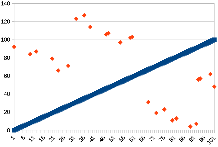
There was suggestive that the graph might be composed of short
line
segments (see where three values are almost in line, twice).
So I extrapolated and tested values programmatically
and my suspicions were confirmed.
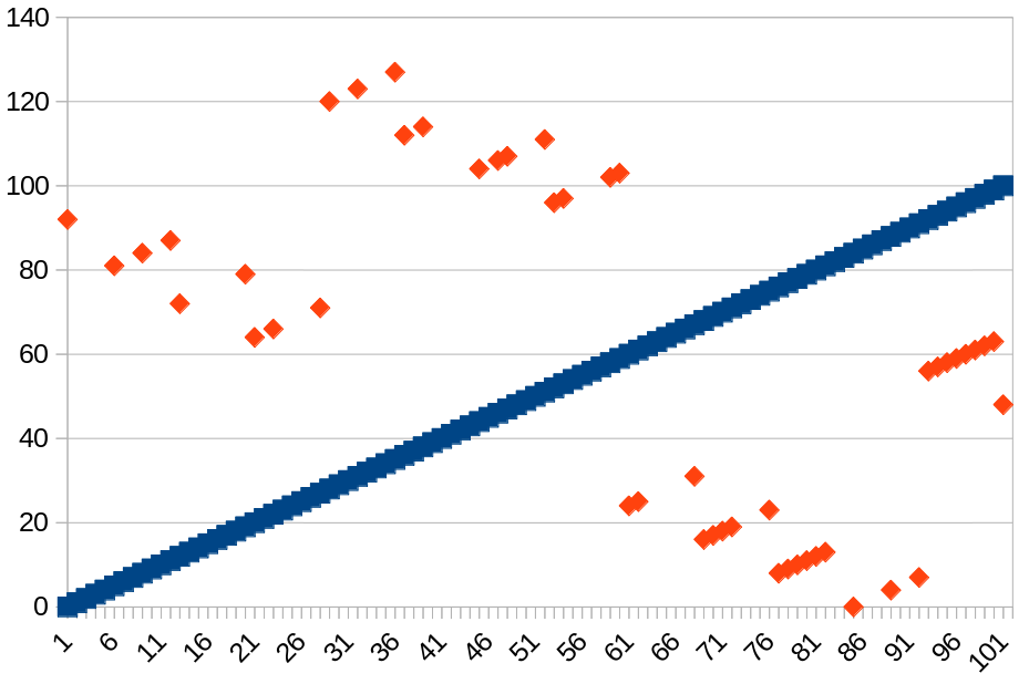
Based on this, I have come up with the following formula for the first byte based on the second byte (the brightness). In decimal:
	0   ≤ byte2 < 3: byte1 = byte2 + 92
	4   ≤ byte2 < 11: byte1 = byte2 + 76
	12  ≤ byte2 < 19: byte1 = byte2 + 60
	20  ≤ byte2 < 27: byte1 = byte2 + 44
	28  ≤ byte2 < 35: byte1 = byte2 + 92
	36  ≤ byte2 < 43: byte1 = byte2 + 76
	44  ≤ byte2 < 51: byte1 = byte2 + 60
	52  ≤ byte2 < 59: byte1 = byte2 + 44
	60  ≤ byte2 < 67: byte1 = byte2 - 36
	68  ≤ byte2 < 75: byte1 = byte2 - 52
	76  ≤ byte2 < 83: byte1 = byte2 - 68
	84  ≤ byte2 < 91: byte1 = byte2 - 84
	92  ≤ byte2 < 99: byte1 = byte2 - 36
	100  ≤ byte2: byte1 = byte2 - 52
	0x00  ≤ byte2 < 0x03: byte1 = byte2 + 5c
	0x04  ≤ byte2 < 0x0b: byte1 = byte2 + 4c
	0x0c  ≤ byte2 < 0x13: byte1 = byte2 + 3c
	0x14  ≤ byte2 < 0x1b: byte1 = byte2 + 2c
	0x1c  ≤ byte2 < 0x23: byte1 = byte2 + 5c
	0x24  ≤ byte2 < 0x2b: byte1 = byte2 + 4c
	0x2c  ≤ byte2 < 0x33: byte1 = byte2 + 3c
	0x34  ≤ byte2 < 0x3b: byte1 = byte2 + 2c
	0x3c  ≤ byte2 < 0x43: byte1 = byte2 - 24
	0x44  ≤ byte2 < 0x4b: byte1 = byte2 - 34
	0x4c  ≤ byte2 < 0x53: byte1 = byte2 - 44
	0x54  ≤ byte2 < 0x5b: byte1 = byte2 - 54
	0x5c  ≤ byte2 < 0x63: byte1 = byte2 - 24
	0x64  ≤ byte2: byte1 = byte2 - 34
You can also download the apk code for the phone and disassemble it. The code is a mess, partly because symbolic constants, variable names and method names have been replaced by a, b, c, ... but also because the code looks a mess anyway! In addition to the switches, the code also seems to handle every other IoT device made by Lanbon. There seem to be quite extensive attempts to obfuscate the data values - either that or the code is really messy :-). I've found where the packets are generated, in method b() of class b in some package, but haven't found where their parameters are set.
Each command is sent to 255.255.255.255 or to the <network address>.255 as a UDP broadcast packet. There is no IPv6 here, only IPv4.
UDP is not a session oriented protocol: there is no expectation that the message is received by anyone, nor that a reply should eventuate. Nevertheless, the Android app expects replies, and will re-broadcast the packet, or eventually timeout on no reply.
Any reply is not a broadcast packet. It is sent between the switch and the app. A third party monitoring the network by wireshark will not generally see such packets. It is supposed to be possible in many cases to set the wireless card into monitoring or promiscuous mode to see all WiFi packets on a LAN, but I guess my luck was out when I tried it: I could only see unicast packets to my wireshark host or broadcast or multicast packets. I tried several machines without success.
There are packet capture apps that can run directly on an Android device, as wireshark is not available. The ones I tried would only see packets for public IP addresses, not the ones on my private LAN that I wanted to look at. I don't know why.
But none of this matters, as I now know enough to send requests programmatically to the switches, and any replies will come back to me. And that is exactly what happens: a successful 33 byte UDP broadcast request is responded to by a 33 byte UDP response back to the requestor. That is, a request to 192.168.1.255 from 192.168.1.125 (my host) is responded to by a reply from 192.168.1.128 (a switch) to 192.168.1.125 (the originating host).
For example, a command to switch both lights on the dual-ganged switch is
0000   aa 21 a0 10 a0 20 15 04 63 86 02 03 00 21 a0 10
0010   00 00 00 00 00 00 00 00 00 00 00 00 00 00 00 00
0020   00
0000   aa 21 0a 10 7a 20 15 04 63 86 02 43 00 00 0a 10
0010   75 20 15 04 63 86 02 40 00 00 0a 10 12 20 15 04
0020   63
The 33 byte reply appears to have the switch ID in bytes 5 to 10, repeated in bytes 17 to 21.
0000   aa 21 0a 10 7a 20 15 04 63 86 02 43 00 00 0a 10
0010   75 20 15 04 63 86 02 40 00 00 0a 10 12 20 15 04
0020   63
0000   aa 21 0a 10 ?? 20 15 04 63 ID ID 23 ?? 00 0a 10
0010   ?? 20 15 04 63 86 02 40 00 00 0a 10 ?? 20 15 04
0020   63
What is interesting is that after a command is accepted by a switch, or certain other commands are recognised, the originating host appears to become some sort of "master". A bunch of messages described later are sent to the master node, until another host becomes the master by sending a command. There only seems to be one master at any time, and only for LAN messages.
Messages sent to a master node are replies to commands, state change messages and 'keep alive' messages.
What is also interesting is that once a command is broadcast, each of the switches now starts sending a 14 byte packet to the originating host every 20 seconds or so. A typical packet is
0000 aa 0e 22 90 20 15 04 63 86 00 00 00 00 00
After a command to turn both lights on, the keep alive message is
0000 aa 0e 23 90 20 15 04 63 86 00 00 03 00 00
The command is only sent to the master node. If this isn't the app, then the app doesn't change state and so gets out of sync.
Like before, much of the packet is unchanged in each message. The only parts that appear to change are
I turned off the internet and then asked the app to discover new devices. It sent about 10 copies of a new message I hadn't seen before:
0000   aa 21 a0 09 59 71 2f 34 05 6c 00 00 0b 00 a0 11
0010   00 00 00 00 00 00 00 00 00 00 00 00 00 00 00 00
0020   00
When I sent this by program, I got (eventually) 33 byte responses from all my switches including the full ID and type:
1-gang switch:
0000   aa 21 0a 09 26 20 15 04 63 83 01 01 00 00 0a 10
0010   c6 20 15 04 63 83 01 00 00 00 0a 10 a7 20 15 04
0020   63

2-gang switch:
0000   aa 21 0a 09 ef 20 15 04 63 86 02 01 00 00 0a 10
0010   2e 20 15 04 63 86 02 20 00 00 0a 10 50 20 15 04
0020   63

Dimmable switch:
0000   aa 21 0a 09 9d 20 15 04 63 93 04 00 00 00 0a 10
0010   78 20 15 04 63 93 04 00 00 00 0a 10 17 20 15 04
0020   63
Perhaps that is the way to enumerate all the devices.
These are complicated. When a master sends a command, it doesn't need to see anything special about, because it knows what is sent. It gets a 33 byte response and after that keep alive msgs are enough. But when a state changes occurs as a result of an internet msg, a 45 byte msg is sent to the master informing it of the state change. An example is
0000   cc 74 23 44 8f 3d c3 90 20 15 04 63 83 2d 0a 19
0010   6c 20 15 04 63 83 01 00 00 a0 00 28 12 00 00 00
0020   00 00 00 00 00 00 00 28 12 00 00 00 00
That is, the master host has sent a command and got a 33 byte acknowledgement. It now gets keep alive msgs from all switches. The app, connected to the internet, now makes a subsequent state change. The master does not see the encrypted msgs. But the switch sends a 45 byte msg to the master telling about it.
So, set the wireshark host into master mode by sending a command. Using the app connect to the internet, change the state of the switches, and observer the 45 byte packets sent to the master. They fall into two groups: one is the single and double ganged switch, the other is the dimmable switch.
The switch ID is in byte 17 to 21. The second nibble of byte 23 is the second byte's second nible e.g. 'both on' has byte '03' with second nibble '3'. The first nibble seems to alternate between '0' and '2' for the single switch and '2' and '4' for the double switch, giving a byte such as '23'.
The value of bytes 17-23 of the previous state msg are repeated in bytes 29-35. So e.g if one state msg is
one on, command 01
0000   cc 74 23 44 8f 3d c3 90 20 15 04 63 86 2d 0a 10
0010   99 20 15 04 63 86 02 21 00 00 0a 10 a3 20 15 04
          ^^ ^^ ^^ ^^ ^^     *
0020   63 86 02 00 00 00 0a 10 e5 20 15 04 63
both on, command 03
0000   cc 74 23 44 8f 3d c3 90 20 15 04 63 86 2d 0a 10
0010   e0 20 15 04 63 86 02 43 00 00 0a 10 99 20 15 04
                                              ^^ ^^ ^^
0020   63 86 02 21 00 00 0a 10 a3 20 15 04 63
       ^^ ^^    **
Similar to the above, but now byte 24 has the dimmming value
ID 2015046393, type 04, 55% dim, value is 0x37
0000   cc 74 23 44 8f 3d c3 90 20 15 04 63 93 2d 0a 10
0010   a6 20 15 04 63 93 04 37 00 00 0a 10 a5 20 15 04
          ^^ ^^ ^^ ^^ ^^    **
0020   63 93 04 00 00 00 0a 10 ec 20 15 04 63
I don't know how to get these yet. Using the management mode to change the name seems to require internet access. That makes sense: the name should be stored on the Lanbon server so that it is available to all apps.
I can't talk to the server as I don't have the right keys.
I have two programs to manipulate my switches. One is a Python program switch.py which is hard-coded with my switches and I use for testing.
The second is a very basic Java Swing GUI application which searches
for switches and then allows control. It doesn't get the
switch names right. It is at
java.zip
and looks like
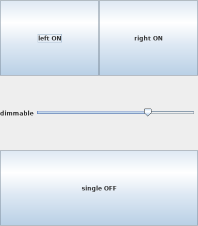 .
.
I have found a partial solution which works for my case. Obviously, others will need variants for their cases. Perhaps if these can be integrated, a more robust solution can be found! The major remaining problem is determining the switch names.