 Ogg-Vorbis format, 8Mbytes
 MP3, 8Mbytes
 WAV format, 85Mbytes
 Ogg-Vorbis format, 8Mbytes
 MP3, 8Mbytes
 WAV format, 85Mbytes
Applications often make use of state information to simplify what is going on. For example
The important point is to whether one process is keeping state information about itself or about the other process. One process may keep as much state information about itself as it wants, without causing any problems. If it needs to keep information about the state of the other process, then problems arise: the process' actual knowledge of the state of the other may become incorrect. This can be caused by loss of messages (in UDP), by failure to update, or by s/w errors.
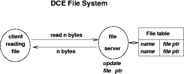
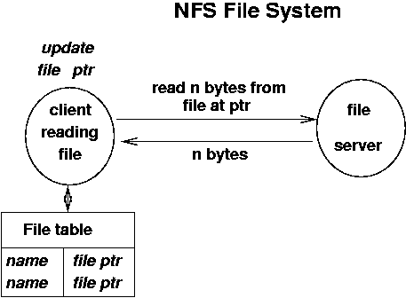
An example is reading a file. In single process applications the file handling code runs as part of the application. It maintains a table of open files and the location in each of them. Each time a read or write is done this file location is updated. In the DCE file system, the file server keeps track of a client's open files, and where the client's file pointer is. If a message could get lost (but DCE uses TCP) these could get out of synch. If the client crashes, the server must eventually timeout on the client's file tables and remove them.


If the server maintains information about the client, then it must be able to recover if the client crashes. If information is not saved, then on each transaction the client must transfer sufficient information for the server to function.
If the connection is unreliable, then additional handling must be in place to ensure that the two do not get out of synch. The classic example is of bank account transactions where the messages get lost. A transaction server may need to be part of the client-server system.
A state transition diagram keeps track of the current state of an application and the changes that move it to new states.
Example: file transfer with login:

This can also be expressed as a table
| Current state | Transition | Next state |
|---|---|---|
| login | login failed | login |
| login succeeded | file transfer | |
| file transfer | dir | file transfer |
| get | file transfer | |
| quit | quit | |
| logout | login |
The client state diagram must follow the application diagram. It has more detail though: it writes and then reads
| Current state | Write | Read | Next state |
|---|---|---|---|
| login | LOGIN name password | FAILED | login |
| SUCCEEDED | file transfer | ||
| file transfer | CD dir | SUCCEEDED | file transfer |
| FAILED | file transfer | ||
| GET filename | #lines + contents | file transfer | |
| ERROR | file transfer | ||
| DIR | #files + filenames | file transfer | |
| ERROR | file transfer | ||
| quit | none | quit | |
| logout | none | login |
The server state diagram must also follow the application diagram. It also has more detail: it reads and then writes
| Current state | Read | Write | Next state |
|---|---|---|---|
| login | LOGIN name password | FAILED | login |
| SUCCEEDED | file transfer | ||
| file transfer | CD dir | SUCCEEDED | file transfer |
| FAILED | file transfer | ||
| GET filename | #lines + contents | file transfer | |
| ERROR | file transfer | ||
| DIR | #files + filenames | file transfer | |
| ERROR | file transfer | ||
| quit | none | quit | |
| logout | none | login |
state = login
while true
    read line
    switch (state)
        case login:
            get NAME from line
            get PASSWORD from line
            if NAME and PASSWORD verified
                write SUCCEEDED
                state = file_transfer
            else
                write FAILED
                state = login
        case file_transfer:
            if line.startsWith CD
                get DIR from line
                if chdir DIR okay
                    write SUCCEEDED
                    state = file_transfer
                else
                    write FAILED
                    state = file_transfer
            ...